Just watched Looper on Blu-ray. Not a bad flick at all. Something that caught my eye were the vehicles. The makers of the film have stated they wanted a sort of a Cuba-ish feel to the vehicles in that there are old beat up vehicles that have obviously been converted to run on something other that originally ran with. Just like they have replaced engines in the old US cars with Soviet diesels (or so I've heard) in Looper they seem to have converted vehicles to run on a variety of fuels.
The main character drives a mint red sports car which seems not to have been modified in any way so it probably still runs on gasoline. Many cars have some added tubing going around the car from exhaust pipe are to gas cap. One of the characters drives an old Japanese motorcycle with some sort of turbine thing replacing the whole lower part of the vehicle. Many cars are also seen with solar panels on all flat surfaces.
That may not be very far from what the future might look like. Gas guzzlers will never go away, but as the price of gasoline will inevitably rise as the supplies eventually dimish a lot less people will want to drive them. It'll be a luxury reserved for the rich and those who restore or keep servicing old classics. Many will just drive on eletricity and some may opt for a fuel cell vehicles. Some will stick to ethanol.
It's just sad that the legislators (fuelled by lobbyists) try to prevent this future of modified vehicles. Let's just hope that tide will turn without the need for a anarchist future like the one depicted in Looper as well.
perjantai 29. maaliskuuta 2013

Spring is coming

It looks like spring is coming. For a nothern motorcyclist the sure signs are increasing amount of dry, ice free asphalt and the accompanying urge to tinker with two wheelers to get them ready for the season. Today I finally did something I had been thinking about since I got the bike inspected last summer. The Cycle Analyst was placed in a less than optimal location below the lock and rather badly in the way, not to mention hard to read while driving. Now it has moved to a better position above the original instrument panel. Looks very good and should be much more user friendly. Good times.
ps. I also lifted the bike on it's center stand, gave the motor a little spin and checked the cells. All came in at 6.56 or 6.57 volts a pair. I'd call that pretty well balanced.
maanantai 25. maaliskuuta 2013
What's wrong with Top Balancing
Let's go over the basics again. Top Balancing is based on a belief that you can fully charge a cell by charging it to a certain voltage, say 3.65 volts, and just keep it there. To get a complete pack "balanced" would require to charge until all cells are at 3.65 volts. To do this some cells need to be kept at 3.65 volts while others catch up. That's all part of Top Balancing and what many BMS do.
So how did they come up with this system that many people swear by and even think to be absolutely necessary? They probably don't know themselves, but here's how I think it must have happened. We know that a LiFePO4 cell likes to stay within a certain voltage range. Go below 2.5 V and you start hurting the cell. Go above 4 V and you're definitely hurting it. To charge a battery you put current into it and since you know you don't want to go over a certain voltage you stop when it's reached. This was 4.2 V in the beginning, but I guess they've found it a little too high since 3.65 V is what most recommend now. They also found out that if you taper the current you can put a little more energy into the cell while keeping the voltage at 3.65 V.
Now think of Lead Acid for a moment. In Lead Acid voltage is voltage and voltage is charge level. You charge and you keep trickle charging your Lead Acid batteries, they'll be happy for it and you get a nicely Top Balanced Lead Acid pack. The more energy you can put into them the happier they are and the more range you will get from you Lead Sled.
Now if you put these two things together, maximum charge voltage and Lead Acid heritage, what you get is Top Balancing and what usually is considered to be a Lithium BMS. To prove this they talk about stuff like Cell Drift and Self Discharge. I really don't know how they came up with them, but it must be from Lead Acid heritage as well. Or maybe they put this Top Balancing BMS on their cells, kept recording the voltages and noticed that they vary and the cells will Self Discharge.
What they didn't think of was that they had the BMS connected the whole time and both phenomena were actually caused by the BMS itself. If you put any Cell Level system on your cells that's not very, very carefully designed not to draw any (and I do mean any) current, you will see the cells react and they will react differently. You will place on uneven load on the cells that will cause "Cell Drift" and the load itself will be the "Self Discharge" you see. To make matters worse, if you Top Balance and keep cells at 3.65 V while other catch up, you will damage your cells and damage them by different amounts, which will only inflate the problems you think are caused by the cells themselves.
But what about internal resistance, you ask. What about it? What part of Top Balancing BMS will have any effect on the internal resistance of the cell? Yes, the cells may have varying internal resistance and that variation will cause them to discharge at a different rate. Let's say you have a pack of cells and you'd charge them each individually to 3.65 volts without damaging them by "boiling" some at that voltage while others catch up. You'd end up with fully charged cells, right? Now what happens when you start discharging them as hard as you can? You know they have different internal resistance and slight variation in capacity, because they just can't make them perfect yet.
So you're discharging and discharging and your first cells hit the cut-off voltage. You have to stop now, or you'll damage those cells. And you'll better be quick about it too. Stop the car immediately. If you were smart you had already put the vehicle into a Crawl Mode, so that you could pull over safely. Unless you've kept a really good track of previous full discharges you won't know when your first cells will be empty and when you should start crawling. Doing so gets really complicated and expensive really fast. Add in all the single cell level monitoring, shunts to enable Top Balancing and it's not really hard to imagine why those BMS systems are so expensive.
Hopefully I've by now convinced you of the problems with and caused by Top Balancing. I'd really like the whole world to get a clue on this, including Boeing and the BMS people at Sähköautot - Nyt! forum, but I don't have my hopes up. What's amazing is how firmly rooted these false beliefs are. It may just be that a lot of people have too much invested in BMS systems to admit there are issues. It sure does seem like a lot of people are looking to make a buck on these.
I guess I still have the obvious question unanswered. If Top Balancing doesn't do what people think it does and if it doesn't really solve anything, what is the answer? How about if we try something quite opposite. Instead of trying to Top Balance the cells we drain them as empty as we dare. 2.5 volts is a little dangerous so let's say 2.75 volts. Let's call that empty, or close enough.
Now if we have all of our cells empty and we connect them in series with just the interconnects we have an empty pack. What happens if we charge them? They will all receive the same amount of current. They're all a little bit different so they absorb their share a little differently, but it doesn't matter. We don't like any cells to go above into dangerous territory so we undercharge a little. We don't even pretend to get all cells at exactly 3.65 volts. Most end up a little below and some may even go a little higher, but it doesn't matter. We accomplish this by charging the whole series pack to cell count times 3.5 volts. My experience is that even with this undercharge you will end up putting as much or even more energy into the cells than what they are rated for.
What you've in essence accomplished by this Bottom Balancing is that you've zeroed all the differences between the cells, whether it be capacity or internal resistance. When you discharge the cells they will do the same thing in reverse that they did when you charged them and if you keep discharging them they will all end up at the same voltage you Bottom Balanced them at. In other words they will both charge and discharge very close the same way. Close enough that it doesn't matter. As a bonus you don't have to keep track of your cells. You'll now exactly how many Ah went into the pack when you charged it and you know exactly how much you can take out. And once those cells hit that 2.5 volts, all together, at the same time, they will be putting out hardly any energy at all. And since they're all empty they can't force each other into destruction.
Disclaimer: All of my battery ramblings are based on my own experience and Jack Rickard's findings. They are applicable to CALB SE- and CA-series cells. Other cells and chemistries may at least require different voltages.
Disclaimer: All of my battery ramblings are based on my own experience and Jack Rickard's findings. They are applicable to CALB SE- and CA-series cells. Other cells and chemistries may at least require different voltages.
keskiviikko 13. maaliskuuta 2013
Hint of progress

The really bad, quick and dirty cell phone photo above depicts the current state of affairs at the kWsaki EV conversion industries. A very kind forum member from the VMPK forums sent me a 350 mm disc of about 17 mm thick aluminium that I was (barely) able to drill a few holes into. Only destroyed an electric drill in the process of making that big hole in the middle, but hopefully I can make this work. Next I'll have to figure out the coupling between the motor and the flywheel. I intend to keep the clutch as a safety feature, if nothing else. Don't worry, I'll make it look all pretty and black eventually.

Update: A coupler pictured here is now on order!
perjantai 15. helmikuuta 2013
Cell drift
Or lack thereof. Yesterday, when the thermometer showed 0 degrees Celsius (or 32 Fahrenheit), I figured it would be time to go check the cells in my kWsaki electric motorcycle. I took the bike off insurance October 3rd so it's been sitting in the cold garage for about four and a half months. I gave one of the TTL-200C motors a quick spin with the kWsaki traction pack and controller, but I haven't recharged since October.
And when I said cold I meant it. The temperature here has regularly been below zero Fahrenheit and the cells have had to endure it. So I was a little excited when I started the measurements. First cell 3.299 V, second 3.299 V, no make it 3.300 V, next 3.299 V, 3.300 V, 3.300 V and so on. It got really boring really fast. I got a little bit of variance when I couldn't reach the terminals of a couple cells and I had to measure them in pairs. They read 6.61 V. A couple cells showed 3.31 V. This was after I had changed the meter's resolution from 0.000 to 00.00. The whole pack registered at 82.8 volts. For 25 cells that's 3.312 V each.
Considering that the meter is no Fluke and it showed a maximum variance of hundredth of a volt, I don't see evidence of cell drift. I've had nothing connected to the pack for these last months. Note that this is the same pack that I pushed down to 2 volts per cell earlier. If I had damaged any of the cells, they probably wouldn't be happily floating at 3.3 volts after being left to their own devices for months.
Conclusions are that cell drift has not been demonstrated and bottom balancing still seems to work.
If I had more money than I can spend, I could have gotten another 25 cells, put a MiniBMS on them and let them idle for over four months. Alas I do not, but the result is easy to guess. Anyone care to prove me wrong?
tiistai 29. tammikuuta 2013
The Shopping List
You may or may not find this interesting, but here's my shopping list for the car as of now.
Already got for the initial build (some of these may get upgraded later):
High priority items needed (car won't run without):
Already got for the initial build (some of these may get upgraded later):
- Thrige-Titan TTL-200C motor
- AXE7245 90V 450A controller
- KP-L 2000W 87.6V charger
- 0-5k throttle
- 25pcs CALB SE40AHA 40 Ah cells
- Cycle Analyst instrumentation
On order at this time:
- Nothing
- Another 25pcs of cells (CALB 40, 60 or 70 Ah, preferably CA-series)
- Motor cooling (EVTV BlowMe or something else)
- Main contactor
Low priority items needed (car won't pass MOT without):
- JLD404 or similar voltage meter for main contactor activation
- DC to DC converter
- Auxiliary 12 V battery
- Vacuum pump (very important)
- PTC or liquid cabin heating (liquid is actually easier, but more expensive)
- High voltage warning stickers everywhere
Vanity items:
- ELECTRIC emblem of some sort
- Braided straps for cell interconnects for improved durability
The list may be incomplete and/or outdated. Just like me.
sunnuntai 20. tammikuuta 2013
How To Bottom Balance
Warning! This article is about LiFePO4 cells. Some of it may or may not apply to other chemistries.
My earlier post on bottom balancing was long and mainly about why to do it. So I figured I might do a little step by step for those who just want to get it done without delving into the philosophy behind.
- Drain all of your cells down to 2.75 volts. Note that the cells will bounce back after you disconnect the load. Repeat the discharge until each cell standing alone stays at 2.75 V.
- Connect your cells to each other. Do not connect anything else between the cells but the bars, straps or fuses connecting cells to each other. Do not install BMS. Do not connect any other wires. Strictly cell interconnects only.
- Charge the battery pack to a voltage of 3.5 to 3.55 volts times cell count. Examples: 25 cells = 87.6 volts = 3.50 per cell, 33 cells = 116.8 volts = 3.54 per cell. Use CC/CV profile which is the default in many LiFePO4 chargers. End charge when total voltage is reached.
- Always discharge the pack as a whole. Always charge the pack as a whole, the same way as described above. Never put any load on only a part of the pack, no matter how small. Never install cell level monitoring or BMS which put any load on individual cells.
If you do this right you shouldn't need to repeat it. If you want, you can periodically drain your pack and measure the voltages. They should all be about the same. If you notice irregularities they are most likely caused by bad cells. Replace bad cells and repeat the bottom balancing for the whole pack.
Bottom balancing is not negligence. Bottom balancing is utmost cell care. You drain them one by one, manually or with a device like Revolectrix PowerLab. While you do that you will spot bad cells quite surely. When you charge them you end the charge well before overcharge and the charge is controlled by the one device which does it best, the charger. As an extra precaution you may also consider adding a meter which disengages the main contactor if pack voltage is not within limits.
On discharge you set your controller to a low voltage limit of over 2 volts per cell (for example, 60 V for 25 cells, 80 V for 33 cells, perhaps even lower). This will prevent any cell going too low, since they all empty at the same time. Since they're all empty they can't harm each other.
Fires happen when cells get overcharged. Bottom balancing doesn't cause overcharging.
Disclaimer: All of my battery ramblings are based on my own experience and Jack Rickard's original work on the subject. They are applicable to CALB SE- and CA-series cells. Other cells and chemistries may at least require different voltages. I take no responsibility for any problems or damage caused by anyone.
torstai 10. tammikuuta 2013
All Quiet on the Western Front
I've been keeping busy with other parts of life, hence no blog posts on EVs in a while. Also I have the car mostly outside, albeit under covers, but still in either bloody cold or nasty damp weather. No warm, dry garage for me at the moment. I have the motorbikes in the garage, but it's still cold.
It doesn't mean my brain has stopped working though and I've been thinking about the projects a lot. I even got around to making some inquiries on the possibility of obtaining some aluminium for the motor adapter plate. Turns out nobody has anything in storage, ordering costs more than actual material and aluminium isn't cheap either. There goes my plan of buying some and playing around with it.
That means it's back to the CAD program and having everything made somewhere based on my drawings. For some reason that also has near zero attractiveness at the moment. Someone on a Citroën forum did point me in the direction of a PSA XU engine brochure which included a priceless picture of the motor with proper measurements and angles of the transmission facing bits. Will make my life a lot easier with the CAD, as soon as I can get around to it.

Reprinted without any permission whatsoever.
I also find myself thinking about battery placement in the kWsaki and dreaming of doubling the amount of SE40AHA cells to get to the 80km+ range I originally had in mind. I think it will happen during spring/summer as well. The kWsara also needs more batteries to move anywhere, so the additional cells will double as both cells for the kWsaki and testing the kWsara.
sunnuntai 9. joulukuuta 2012
Motor adapter plate
I also made a template for the motor adapter plate from a piece of particle board I found lying around.


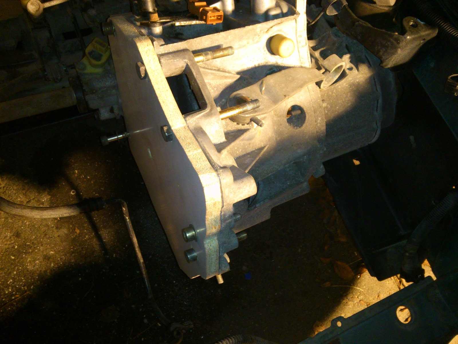
If you look closely you may also notice that the transmission has gotten a little cleaner than before. I washed the engine compartment as well as I could given the circumstances. The adapter template should allow me to either make a CAD drawing for a complete part to be manufactured at a shop or perhaps I'll just make a copy of it using a sheet of suitably thick aluminium. We'll see which will come to be.
Leevi
Here's an interesting product I accidentally came across this morning. It's a little device that's meant to automatically switch between engine and cabin heaters in the winter. First it heats the engine and then switches to cabin heating until the engine cools too much. My idea is to use it to first heat the battery pack and when it's built in heat sensor detects the pack temperature to be at +5 Celsius it will switch on the cabin plug in which I have connected my charger. In essence making sure that charging won't be started unless there's sufficient heat in the battery box. I'm assuming I can safely leave it in all year and once it gets cold enough it just starts doing it's thing.


Their web page is here http://www.leevi.org and you can also buy them here http://kauppa.motonet.fi/motonet/tuotteet/454943/0. It's compatible with the usual Defa heating system. Simple and convenient. Gotta love it.
Tilaa:
Blogitekstit (Atom)